
Choosing the best Ceramic Thermal Paste is not a simple search for the highest thermal conductivity number. A cooler, processor, or graphics card can behave differently under real working conditions. The paste must fill microscopic surface imperfections between the chip and heatsink. It should also remain stable during repeated heating and cooling.
Roman “der8auer” Hartung, a respected overclocking specialist, explains: “Thermal paste is only there to fill the microscopic gaps between the surfaces.” That principle keeps the decision practical. A thick paste may perform well on a desktop processor, yet spread poorly on a small laptop chip. A very thin formula may spread easily but lose stability over time. Tiny details matter.
This guide examines the properties behind reliable Ceramic Thermal Paste selection. We will consider thermal conductivity, viscosity, curing behavior, pump-out resistance, application methods, and electrical safety. Compatibility deserves attention too. Some pastes work well with copper and nickel-plated surfaces, while others may behave differently on aluminum.
Real testing is more useful than a dramatic package claim. A one-degree difference may disappear because of room temperature, mounting pressure, or fan speed. That can be disappointing. It is also why careful comparisons matter.
Readers will learn how to match paste characteristics with their actual hardware, workload, and maintenance habits. The “best” product is not universal. It is the one that stays consistent inside your system. Sometimes, the ideal choice is not the most expensive tube.
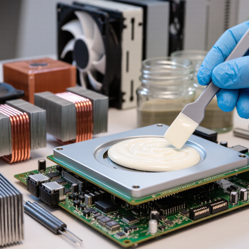
Ceramic thermal paste is a heat-transfer compound filled with electrically insulating ceramic particles. It sits between a processor and heatsink, filling microscopic air gaps. Air is a poor conductor, while ceramic fillers transfer heat more effectively. Most products fall between 3 and 8 W/m·K in stated thermal conductivity. This range is useful, but it is not the whole decision.
A 3 W/m·K paste may suit ordinary office computers and moderate workloads. Higher-performance systems can benefit from 6–8 W/m·K material. However, published conductivity values come from controlled laboratory tests. Real results depend on layer thickness, mounting pressure, surface flatness, and operating temperature. I have seen a high-rated paste perform poorly when applied too thickly. Less can be more.
Check the paste’s viscosity before buying. A thick compound may bridge uneven surfaces, but it can spread unevenly. A softer paste usually forms a thinner layer with less effort. Ceramic formulas are often preferred when electrical insulation matters near exposed contacts. Still, insulation should be confirmed in the technical data, not assumed from the word “ceramic.” Apply a small, even amount and inspect the contact pattern after mounting when possible. That extra check feels excessive. Sometimes it reveals a warped surface, trapped air, or insufficient pressure. Choose based on the complete installation, not conductivity alone.

Choosing ceramic thermal paste starts with the heat load, not a high conductivity number. A desktop CPU may face short power spikes, while a GPU often sustains heat across a larger die. Check typical and peak wattage, then consider cooler capacity and case airflow. Thermal conductivity, measured in W/m·K, describes how quickly heat moves through the paste. It does not guarantee lower temperatures by itself. A thin, continuous layer usually performs better than a thick coating.
Thermal resistance is often more useful for comparison. Measured in °C/W, it estimates temperature rise at a given load. Lower resistance is preferable. For example, at 150 watts, a 0.05 °C/W interface could add about 7.5 °C. That figure ignores mounting pressure and surface flatness. Real systems are less tidy. Paste can spread unevenly around a GPU’s wide contact area, especially when the cooler flexes. A ceramic compound with moderate conductivity but stable resistance may beat a higher-rated product applied poorly.
During installation, clean both surfaces with suitable isopropyl alcohol and let them dry fully. Apply enough paste to fill microscopic gaps, not enough to form a visible ridge. For direct-die cooling, coverage deserves extra attention. I once focused too much on conductivity and overlooked pump-out after repeated heat cycles. That mistake raised temperatures weeks later. Monitor temperatures under the workload you actually run, using consistent fan settings and room conditions. Compare sustained readings, not one brief benchmark. Numbers matter. Pressure matters too. If resistance data is missing, treat impressive conductivity claims cautiously and consult the technical sheet.
Match thermal conductivity and resistance to CPU or GPU heat loads
Reading the chart: The bars estimate the temperature rise across a 0.10 mm paste layer covering a 10 cm² contact area. Higher-conductivity ceramic formulations produce lower thermal resistance and a smaller temperature increase.
Reference conditions: Alumina: 3 W/m·K, boron nitride: 6 W/m·K, aluminum nitride: 10 W/m·K, and a high-conductivity ceramic hybrid: 12 W/m·K. Actual results vary with bond-line thickness, mounting pressure, surface flatness, and application quality.
Viscosity controls how easily ceramic paste spreads and fills microscopic surface gaps. A paste that is too thin may squeeze out during clamping. A paste that is too thick can trap air or require excessive dispensing pressure. In production testing, measure flow at the actual nozzle, temperature, and pressure. ASTM D5470-17 emphasizes controlled contact pressure because test conditions strongly influence thermal resistance. Do not trust viscosity alone.
Application thickness deserves equal attention. Many thermal interface studies target bond lines near 50–100 micrometers for flat, well-machined surfaces. Thicker layers usually add thermal resistance, even when conductivity looks impressive on a datasheet. Use a controlled stencil, spacer, or calibrated dispenser. Check the compressed layer at several points, not only its center. A perfect-looking spread can still hide voids.
Pump-out performance matters during repeated heating and cooling. Ceramic particles do not eliminate movement caused by different expansion rates between a chip, heat spreader, and heatsink. JEDEC JESD51-14 supports transient testing methods that help separate interface resistance from surrounding thermal effects. For qualification, combine thermal cycling, vibration, and post-test thickness inspection. I would not select the “smoothest” paste automatically. A slightly harder material may resist migration better, but it can complicate assembly and increase contact pressure. The best choice remains application-specific, and that is easy to underestimate.
Ceramic filler does not automatically mean electrical insulation. Verify the paste’s dielectric strength and volume resistivity in its technical documentation. Choose data measured under recognized laboratory conditions, not vague claims such as “non-conductive.” Check the continuous operating temperature, short-term peak temperature, and recommended storage range. A product rated above 150°C should still provide a clear safety margin for your application. Numbers matter here.
During practical testing, I inspect the material around pins, solder joints, and exposed traces. At 160°C, small gaps can become important after repeated heating and cooling.
Thermal cycling may cause pumping, drying, or separation between the component and heatsink. A stable paste should remain evenly distributed without creating a hard, cracked edge.
Apply only the amount needed to fill microscopic surface marks. Too much can increase thermal resistance.
I once trusted a “ceramic” label and skipped the insulation test. That was careless.
For reliable selection, test a small assembly under its real voltage, pressure, and temperature conditions. Measure insulation resistance before heating and after several thermal cycles. Also check the safety data sheet and batch information.
Consistent viscosity helps during production, but it does not replace electrical verification. Record application thickness, curing behavior, and contact pressure, because these details can change results more than expected.
Choosing ceramic thermal paste requires more than comparing thermal conductivity figures. Cure time can change installation decisions. Some formulations remain workable after application, while others need controlled heating or room-temperature curing. Check the technical data sheet for cure temperature, humidity, bond-line thickness, and full-cure time. A “24-hour cure” is not meaningful without test conditions. ASTM D5470 is widely used to measure thermal impedance, but results depend heavily on pressure and layer thickness.
Shelf life deserves equal attention. A recent thermal interface materials market report by MarketsandMarkets identifies electronics cooling as a major demand area, increasing the need for stable, repeatable materials. Still, market growth does not prove product reliability. Inspect the stated storage range, unopened shelf life, batch date, and post-opening handling rules. A paste stored in a hot workshop may separate before its printed expiry date. It happens.
Ask manufacturers for lot-specific test results, not only catalog averages. Useful evidence includes ASTM D5470 thermal resistance, thermal cycling data, viscosity retention, and adhesion changes after aging. JEDEC JESD51-14 can support semiconductor thermal characterization, although it does not replace paste-specific testing. In practical trials, record surface temperature, mounting pressure, application weight, and cure conditions. Even a small difference in paste thickness can distort comparisons. My own preference is cautious: repeat each test several times. One clean result may be luck.
Please fill out this form and we will get an order or estimate ready for you. Please give us as much detail as you can for us to get started, and we will contact you to finsh the work order.